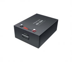
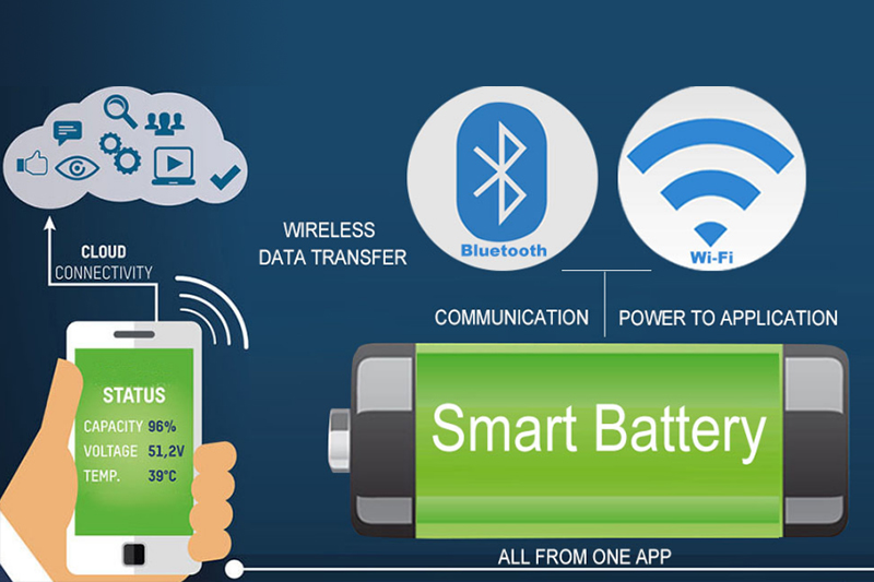
3.7V lithium battery protection board single-cell lithium battery
protection circuit principle analysis
There are many specific composition schemes for single-cell lithium battery
charging and discharging protection circuits, but the working principles are not
much different. The following is an example of a circuit that is used more in
mobile phones for analysis for reference.
1. Single-cell lithium battery protection circuit
There are many specific composition schemes for the charging and
discharging protection circuit of a single-cell lithium battery, but the working
principle is not much different. The following is an example of a circuit that
is used more in mobile phones for analysis for reference.
The control chip of this circuit is DW01 (or 312F), and the MOS switch is
8205A. As shown in Figure 6, B+ and B- are the positive and negative terminals
of the battery cell; P+ and P- are the positive and negative outputs of the
protection board. Negative; T is the temperature resistance (NTC) port, which
generally needs to cooperate with the CPU of the electrical appliance to perform
protection control.
DWO1 or 312F is a lithium battery protection chip with a built-in
high-precision voltage detection and time delay circuit. The main parameters are
as follows: overcharge detection voltage is 3V, overcharge release voltage is
4.05V; overdischarge detection voltage is 2.5V , Over-discharge release voltage
is 3.0V; over-current detection voltage is 5V, short-circuit current detection
voltage is 1.0V; DW01 allows the maximum current output of the battery is 3.3A.
The pin function of this chip is shown in Table 1.
(1) Normal work
The circuit of the protection board is shown in Figure 7. When the cell
voltage is between 2.5V and 4.3V, pins ① and ③ of DW01 both output high level
(equal to the supply voltage), and the voltage of pin ② is 0V. At this time, the
two N-channel field effect transistors Q1 and Q2 in the 8205A are in the
conducting state. Since the on-resistance of the 8205A is very small, it is
equivalent to a direct connection between the D and S poles. At this time, the
negative pole of the cell and the P of the protection circuit The-terminal is
equivalent to a direct connection, the protection circuit has a voltage output,
and its current loop is as follows: B+→P+→load. P-→foot ②, ③ of 8205A→foot ① of
8205A→foot ⑧ of 8205A→foot ⑥, ⑦ of 8205A→B-.
(2) Over-discharge protection
When the battery cell is discharged through an external load, the voltage
at both ends of the battery cell will slowly decrease. At the same time, the
DW01 will monitor the cell voltage in real time through the resistor R1. When
the cell voltage drops to 2.3V (usually called the over-discharge protection
voltage) ), DWO1 considers that the cell is already in an over-discharged state,
its voltage at pin ① becomes 0, and Q1 in 8205A is cut off. At this time, the
cell's B- and-are in a disconnected state, that is, the discharge circuit of the
cell is cut off. , The battery cell will stop discharging.
After entering the over-discharge protection state, the cell voltage will
rise. If it can rise to the IC's threshold voltage (usually 3.1V, usually called
the over-discharge protection recovery voltage), the pin ① of DW0 will return to
the output high level, and the voltage in 8205A Q1 turns on again.
(3) Charging the battery
Regardless of whether the protection circuit enters the over-discharge
state, as long as the charging voltage is added between the P+ and P- terminals
of the protection circuit, after DW0 detects the charging voltage through the B
terminal, it immediately outputs a high level from pin ③, and Q2 in 8205A
conducts Pass, that is, the P- pass of the B-protection circuit of the battery
cell, the charger charges the battery, and the current loop is as follows:
charger positive→p+→B+→B-, ⑥, ⑦ pin of 8205A → pin ⑧ of 8205A→ Pin ① of
8205A→pin ②, ③ of 8205A→P-→the negative pole of the charger.
(4) Overcharge protection
When charging, when the battery is normally charged by the charger, as the
charging time increases, the voltage at both ends of the cell will gradually
increase. When the cell voltage rises to 4.4V (usually called the overcharge
protection voltage), DW01 It will be judged that the battery cell is already in
the overcharged state, and the voltage of pin ③ will be immediately reduced to
0V. Q2 in 8205A will be cut off because pin ④ is low. At this time, the B pole
of the cell and the P- terminal of the protection circuit will be cut off. It is
in the disconnected state and maintained, that is, the charging circuit of the
battery cell is cut off, and the charging is stopped.
When the P+ and P- terminals of the protection circuit are connected to the
discharge load, although Q2 is cut off, the forward direction of the diode
inside is the same as the current direction of the discharge circuit, so the
load can still be discharged. When the voltage at both ends of the cell is lower
than 4.3V (usually called the overcharge protection recovery voltage), DW01 will
exit the overcharge protection state, pin ③ will output high level again, and Q2
will be turned on, that is, the B- terminal of the cell is connected with The P-
terminal of the protection circuit is reconnected, and the battery cell can be
charged and discharged normally.
(5) Overcurrent protection
Since the MOs switch tube also has internal resistance when it is saturated
and turned on, there will be a voltage drop between the D and S poles of the MOs
switch tube when current flows. The protection control IC will detect the
voltage of the D and S poles of the MOs switch tube in real time. When the
voltage rises to the IC protection threshold (usually 0.15V, called the
discharge overcurrent detection voltage), the discharge protection execution end
immediately outputs a low level, the discharge control MOs switch tube is turned
off, and the discharge circuit is disconnected.